Configuring keypoint-based object detection
An exercise in detecting an image using keypoint detection.
Ensure that you have done the following:
Captured and saved a baseline image.
Captured at least one image similar to the baseline image, or containing an object of interest that is similar to an object in the baseline. This is your training image; save it as a .png file.
注意:- To capture screenshots of desktop applications, use the Picture Capturing tool.
- To capture screenshots of mobile applications, use the Device Live Screen tool together with the Picture Capturing tool.
Keypoint image detection, as opposed to pixel-by-pixel detection, is a useful picture handling technique when you are dealing with test images that may vary somewhat from the baseline, or the need to find multiple instances of an “object” within a test image. For more on TestArchitect’s keypoint detection process, refer to Keypoint object detection.
In the following example, we wish to find the presence of a given object (a Rubik’s cube) within the test image. We have already captured and saved a baseline image containing a sample of the Rubik’s cube image, and have saved a training image containing the object of interest, along with additional content.
In the TestArchitect explorer tree, double-click a baseline image node.
You can select a baseline image from either a shared or a regular picture check.
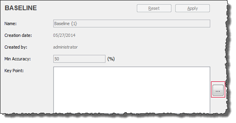
In the Baseline tab, click the Browse
 button next to the Key Point field.
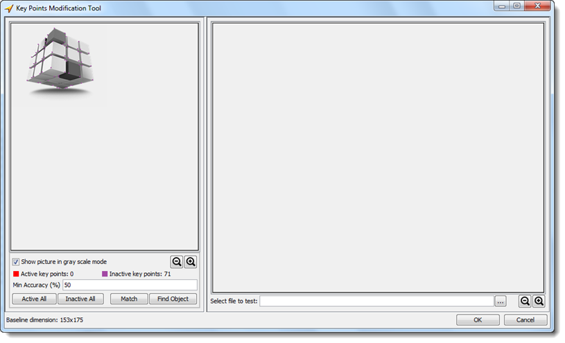
Immediately after the Key Points Modification Tool dialog box appears, TestArchitect automatically applies an image processing algorithm to establish a set of keypoints for the baseline image. These appear as a set of colored dots in the baseline image. In the figure below, a total of 71 keypoints have been established for the baseline image. They are all in the inactive state, as indicated by their purple color.
 ヒント:
ヒント:- Use the
 and
and  buttons to zoom in or out on the baseline image, respectively, to better help you visualize the locations of keypoints.
 - The Show picture in gray scale mode check box is selected by default. By displaying the image without color, the colored keypoints are, again, easier to detect by eye. You may clear the check box if you wish.
- The Min Accuracy (%) box allows you to specify a threshold of similarity between the baseline object defined by the set of active keypoints and any given portion of the test image (or, at this point, the training image) that appears to be a match. Any training image region whose accuracy rating is equal to or greater than this threshold is treated as a detected object. The default value is 50.
- Use the
It’s often the case that you will want to limit the area of the baseline that will be used for finding a match with the captured image, or, more likely, with a portion of the captured image.
Optional: Select a rectangular keypoint region by clicking on a starting point in the baseline image and dragging the mouse pointer while holding the left mouse button.
A red rectangle appears while you drag the mouse pointer to define the selected region.
Release the mouse button when you’ve established the region you want.
The keypoints in the selected region are highlighted in green, indicating that they are selected.
Click the Active All button to enable the selected keypoints.
TestArchitect highlights the selected keypoints in red to indicate they are in the Active state. The number of active keypoints is displayed in the Active key points field.
Optional: If you want TestArchitect to recalculate the number of active keypoints, do the following steps:
Click the Inactive All button to reset the Active key points and the Inactive key points fields.
Repeat through steps #3 and #4 to reselect another region of keypoints.
Click the Active All button
TestArchitect recalculates the number of active keypoints in the new selected region.
After defining the number of active keypoints within the baseline image, click the Browse
 button next to the Select file to test field to open a training image.
In the Select dialog box, browse to the appropriate image file, then click the Select button.
The selected image is displayed in the Training Image panel.
Click the Match button to find the closest keypoint matches of the training image with the baseline’s active keypoints.
Each matched pair of keypoints is connected through a single line.
A divergent keypoint is one which is visibly outside of a matching object in the training image, but which has been selected as the closest match for a given active keypoint in the baseline. If there are any divergent keypoints, you can opt to exclude them, either individually or en masse. (Note: Removing a few divergent keypoints may improve the accuracy of your object matching. But also note that this preliminary matching of keypoints is not an exclusive process. When you click Match, TA uses a narrow set of criteria to determine the best training keypoint match for each active baseline keypoint. But other training keypoints may be “close seconds” as matches, and they will be considered later as possible matches when you tell TA to search for object matches (that is, when you click Find Object). In fact, during object matching, TA accepts that there may be multiple matching objects in the training image, which it finds by allowing for a one-to-many relationship between each baseline keypoint and training image keypoints. So don’t get too hung up on individual divergent keypoints, they’re often not a problem.)
Click the Clear button to clear all of the existing connected lines
Select a region of keypoints which you want to exclude by clicking the starting point and, while pressing the left mouse button, dragging the mouse cursor to the end point.
A red rectangle appears while you are dragging the mouse cursor to highlight the selected region.
Click the Inactive all button to deactivate the selected keypoints.
Click the Match button again to start finding corresponding pairs of keypoints between images.
After finding corresponding pairs of keypoints between images, click the Find Object button to use these pairs to match the baseline image and the target image.
The matching process is based on the number of active keypoints and the minimum accuracy percentage, specified in the preceding steps.
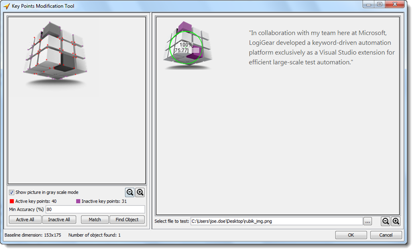
The matched object(s) are detected and then marked inside a green circle along with their accuracy percentage, and (x, y) coordinates.

Click OK .

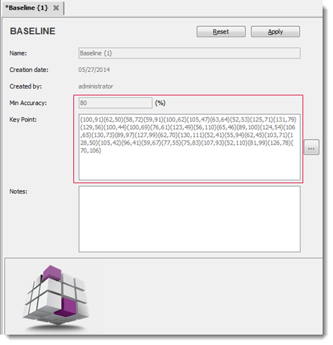
- A set of keypoint locations is saved in the Key Point field in the Baseline tab. These are the keypoints that define the baseline object. Each keypoint is defined by its (x, y) coordinates.
- The value specified in the Min Accuracy (%) field of the Key Points Modification Tool dialog box is also updated in the Min Accuracy field.
Click Apply to save the changes.
You may now use the newly established keypoint-based baseline object within your picture handling built-in actions to detect objects in tested images during automated testing. However your test must first set the built-in setting picture algorithm to the value key points to activate keypoint detection as the active picture handling technique.
Related concepts
